
QTR-8RC Compatible 8-Channel Infrared Reflectance Sensor
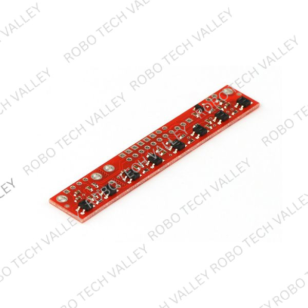
This module is a high-performance, cost-effective reflective sensor array designed for line-following robots and proximity detection. Based on the QTR-8RC architecture, it features eight infrared LED/phototransistor pairs arranged on a precise 9.525 mm (0.375″) pitch.
Unlike standard analog sensors, this module utilizes an RC decay method, allowing it to interface directly with digital I/O lines on microcontrollers (such as Arduino, ESP32, or STM32) without requiring an Analog-to-Digital Converter (ADC). It supports both 3.3V and 5V logic, making it highly adaptable for various robotic platforms.
Note: This is an imported compatible module (functionally identical to the Pololu QTR-8RC) featured by Robo Tech Valley.
Key Features
-
8-Point Detection System: Contains 8 independent IR sensor pairs for high-resolution line tracking or surface sensing.
-
No ADC Required: Uses a digital I/O-compatible RC discharge sensing method, freeing up analog pins on your microcontroller.
-
Power Efficient: LEDs are arranged in pairs to halve current consumption. Includes a MOSFET switch to turn off LEDs when not in use or to control brightness via PWM.
-
Dual Voltage Support: Designed for 5V systems but includes a dual-stage resistor setup that can be bypassed for optimal 3.3V operation.
-
High-Speed Sensing: Capable of sampling rates up to 1 kHz, ideal for fast-moving competition robots.
-
Compact Form Factor: Lightweight and flat design meant to be mounted parallel to the ground (3mm to 6mm height recommended).
Functional Overview: How it Works
The Digital “RC Decay” Method
This sensor does not output a standard analog voltage. Instead, it operates on a charge-and-discharge timing principle:
-
Charge: The microcontroller sets the I/O line to output HIGH, charging the internal node.
-
Read: The microcontroller switches the I/O line to input (high impedance).
-
Measure: The voltage decays as the phototransistor draws current based on the reflection it sees. The microcontroller measures how long it takes for the voltage line to drop to LOW.
-
Short decay time = High reflection (White surface)
-
Long decay time = Low reflection (Black line/Void)
-
LED Control & Power
Current Draw: approximately 20–25 mA per LED pair, with a total board consumption of just under 100 mA.
-
MOSFET Switching: The on-board MOSFET gate is normally pulled high (LEDs ON). By driving this pin LOW, you can turn off the LEDs to save power or use PWM to adjust sensitivity and brightness.
Typical Applications
-
Line Following Robots: Ideal for PID-based line tracking algorithms (black line on white background or vice versa).
-
Maze Solvers: Accurately detects intersections and grid patterns.
-
Sumo Bots: Edge detection to prevent falling off the arena (Dohyo).
-
General Automation: Proximity sensing and object alignment in DIY electronics.
Technical Specifications Summary
| Feature | Description |
| Sensor Type | IR Reflectance |
| Channels | 8 |
| Operating Voltage | 3.3V – 5V DC |
| Pitch | 9.525 mm (0.375″) |
| Output Type | Digital I/O (Timing based) |
| Max Sampling | 1 kHz |



Reviews
There are no reviews yet.