

Adafruit 16-Channel 12-bit PWM/Servo Driver
You want to make a cool robot, maybe a hexapod walker, or maybe just a piece of art with a lot of moving parts. Or maybe you want to drive a lot of LEDs with precise PWM output. Then you realize that your microcontroller has a limited number of PWM outputs! What now? You could give up OR you could just get this handy PWM and Servo driver breakout.
Specifications:
- Dimensions (no headers or terminal block) 2.5″ x 1″ x 0.1″ (62.5mm x 25.4mm x 3mm)
- Weight (no headers or terminal block): 5.5grams
- Weight (with 3×4 headers & terminal block): 9grams
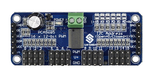
- This board/chip uses I2C 7-bit address between 0x40-0x7F, selectable with jumpers
Power Pins
- GND – This is the power and signal ground pin, must be connected
- VCC – This is the logic power pin, connect this to the logic level you want to use for the PCA9685 output, should be 3 – 5V max! It’s also used for the 10K pullups on SCL/SDA so unless you have your own pullups, have it match the microcontroller’s logic level too!
- V+ – This is an optional power pin that will supply distributed power to the servos. If you are not using for servos you can leave disconnected. It is not used at all by the chip. You can also inject power from the 2-pin terminal block at the top of the board. You should provide 5-6VDC if you are using servos. If you have to, you can go higher to 12VDC, but if you mess up and connect VCC to V+ you could damage your board!
Control Pins
- SCL – I2C clock pin, connect to your microcontrollers I2C clock line. Can use 3V or 5V logic, and has a weak pullup to VCC
- SDA – I2C data pin, connect to your microcontrollers I2C data line. Can use 3V or 5V logic, and has a weak pullup to VCC
- OE – Output enable. Can be used to quickly disable all outputs. When this pin is low all pins are enabled. When the pin is high the outputs are disabled. Pulled low by default so it’s an optional pin!
Output Ports
There are 16 output ports. Each port has 3 pins: V+, GND and the PWM output. Each PWM runs completely independently but they must all have the same PWM frequency. That is, for LEDs you probably want 1.0 KHz but servos need 60 Hz – so you cannot use half for LEDs @ 1.0 KHz and half @ 60 Hz.
They’re set up for servos but you can use them for LEDs! Max current per pin is 25mA.
There are 220 ohm resistors in series with all PWM Pins and the output logic is the same as VCC so keep that in mind if using LEDs.
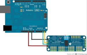
Connecting to the Arduino
The PWM/Servo Driver uses I2C so it take only 4 wires to connect to your Arduino:
“Classic” Arduino wiring:
- +5v -> VCC (this is power for the BREAKOUT only, NOT the servo power!)
- GND -> GND
- Analog 4 -> SDA
- Analog 5 -> SCL
Older Mega wiring:
- +5v -> VCC (this is power for the BREAKOUT only, NOT the servo power!)
- GND -> GND
- Digital 20 -> SDA
- Digital 21 -> SCL
R3 and later Arduino wiring (Uno, Mega & Leonardo):
(These boards have dedicated SDA & SCL pins on the header nearest the USB connector)
- +5v -> VCC (this is power for the BREAKOUT only, NOT the servo power!)
- GND -> GND
- SDA -> SDA
- SCL -> SCL
Subscribe our YouTube channel:


1 review for 16-Channel 12-bit Servo Driver
There are no reviews yet.